


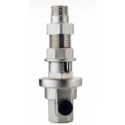
Reducer
 |
|
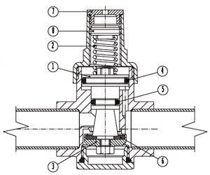
1. Pistone 2. Molla di taratura 3. Otturatore 4. Guarnizione O-Ring 5. Guarnizione O-Ring piccola 6. Guarnizione Otturatore 7. Tappo superiore 8. Ghiera di taratura |
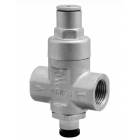
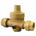
FUNCTION AND USE
The pressure reducing valve is a device that enables to reduce and maintain (to a preset value), the output pressure of a fl uid. The outlet pressure can be adjusted (within a range specifi ed by the manufacturer) using the calibration screw. The whole range of pressures reducers, from DN 3/8” to DN 2”, are with compensated action and characterized by a system with pressure regulating piston which ensures that the output pressure is not aff ected by pressure variations that may be present upstream the reducer.
It also gives to Reducers high robustness and reliability, as well as a high accuracy in regulation. They can be directly connected to the main supply line system, where it is possible to have extremely high pressures (Max Pressure 25 bar). Because of their particular size and ruggedness are suitable to be used in systems for small users, such as apartments or single-family homes, as well as for industrial plants, always with pressures lower than 25 bar.
OPERATION PRINCIPLE
The pressure reducer functioning is based on the balancing of two opposing forces over the piston: to one side, the downwards thrust of the spring (to allow passage of fluid), and to the other, the upward thrust created by the fluid pressure (to reduce or stop the passage of the fluid).
At the moment when there is a fl uid delivery, the spring force prevails over the fl uid pressure, consequently the obturator moves downwards, allowing the passage of fluid. For a greater demand for fl uid, there will be a greater aperture.
In the moment when ends the delivery of the fl uid, the pressure in the system increases pushing up the piston and bringing the obturator to close.
The control system, without membrane, gives to the reducing system a high strength and reliability. The O-ring seals of Piston and obturator are subject to deterioration while ensuring an adequate period of use.
THE SELECTION
To determine which kind of reducer to use in the installation, it will need to consider the diff erent specifi cations of the various models in the range; diagrams 1 and 2 may be help for the dimensional choice in function of the flow
and the type of fluid used.
Diagram 1 shows the flow corresponding to the speed of fluid flowing in the pipes for the diff erent diameters.
Diagram 2 shows the values relating to the pressure flow drop (values related to water) that remain almost constant regardless of the pressure. The selection of the reducer to use is generally based on the speed of fluid fl owing in the pipes, which must always be less than 2 m/sec (water) and 20 m/sec (air). It is also recommended to calculate the installation to ensure that the pressure loss is not greater than 1.2 bar.
INSTALLATION
• The reducer must be installed by a qualifi ed technician in accordance with the national regulations.
• Pressure reducing valves can be installed in horizontal or vertical position, respecting the fl ow passage direction indicated by the arrow printed on the body.
• After the fi rst installation it is recommended to run the water to eliminate any air bubbles from the plant
• It is recommended to install a fi lter upstream of the reducer.
• in presence of aggressive water, it is important to provide a treatment system at the input to the supply plant to protect all the elements of the system.
• To facilitate the maintenance operations it is suggested the installation of valves, both upstream and downstream of the reducer.
• The reducers are supplied with a factory setting from 2 and 3 bars. To adjust the calibration should remove the upper cap from the cover and turn the adjusting screw. By turning the adjusting screw clockwise to increase the outlet pressure, counterclockwise to decrease it. The adjustment and monitoring of the outlet pressure must be carried out in static conditions of water flow
• In the case of installation of a boiler, to avoid the pressure increase due to the water heating, it is suggested the installation of an expansion vessel.
• It is not recommended to install pressure reducing valves in underground wells.
|
|
|
|
|
|
|
|
|
|
|
|
|
|
|
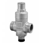
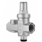
PRESSURE REDUCERS STANDARD series
The STANDARD series, the appropriate size to the provision of a high flow and high stability, it is suitable to be used for civil good-sized plants, multi-family apartments, villas, or on industrial plants for inlet pressures up to 25 bar.
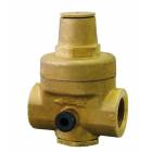
CONSTRUCTIONAL FEATURES
• Rated plant pressure PN 25
• Compensated action with housing and body in EN 12165 - CW 617N
• Sandblasted or nickel-plated version on request
• Calibration spring in special steel
• Maximum reduction ratio: 1:10
• Maximum pressure upstream: 25 bars
• Calibration range: 1.0 - 4.5 bars (H.D. version 2.0 - 9.0 bars)
• Seals: EPDM
• Maximum temperature of fl uid (water) 80°C (in version with VITON seals 130°)
• Threaded sockets ISO 228/1
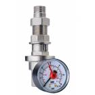
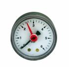
• Sockets for output pressure reading manometer, sealed with plastic threaded plug-ring nut F 1/4” ISO 228/1
• Tests and inspections: EN 1567
All the reducers in the STANDARD series are inspected and calibrated in production at an output pressure between 2 and 3 bars.
The STANDARD series, the appropriate size to the provision of a high flow and high stability, it is suitable to be used for civil good-sized plants, multi-family apartments, villas, or on industrial plants for inlet pressures up to 25 bar.
CONSTRUCTIONAL FEATURES
• Rated plant pressure PN 25
• Compensated action with housing and body in EN 12165 - CW 617N
• Sandblasted or nickel-plated version on request
• Calibration spring in special steel
• Maximum reduction ratio: 1:10
• Maximum pressure upstream: 25 bars
• Calibration range: 1.0 - 4.5 bars (H.D. version 2.0 - 9.0 bars)
• Seals: EPDM
• Maximum temperature of fl uid (water) 80°C (in version with VITON seals 130°)
• Threaded sockets ISO 228/1
• Sockets for output pressure reading manometer, sealed with plastic threaded plug-ring nut F 1/4” ISO 228/1
• Tests and inspections: EN 1567
All the reducers in the STANDARD series are inspected and calibrated in production at an output pressure between 2 and 3 bars.