|
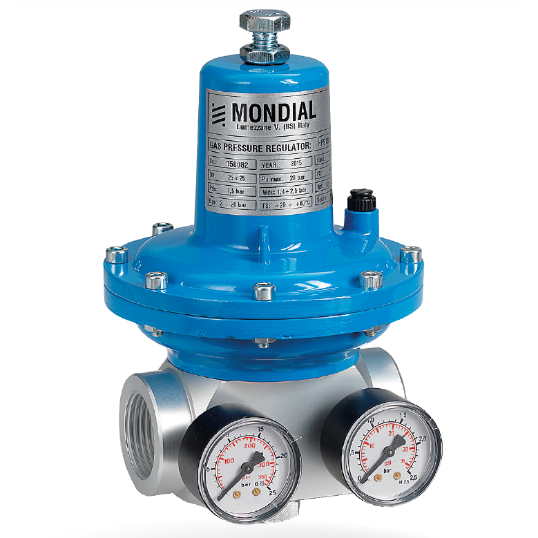
HPS100
Main features:
-
Medium/high pressure setting
-
High regulation accuracy
-
High flow rate
-
Spring loaded
-
EN 334 compliance
-
Threaded and flanged connections DN 25x25
-
Compact design
-
Easy maintenance
-
Internal or external adjustment
On request:
-
Inlet and outlet pressure gauges
-
Low pressure setting
-
Integrated relief valve
-
External pulse
Application: HPS 100 regulator is suitable to reduce gas pressure for industrial and commercial applications, for medium and high pressure. Designed to deliver high regulation accuracy, this device is suitable for use with non-corrosive gases, previously filtered. HPS 100 regulator is widely used in natural gas, manufactured and LP gas plants, in both civil and industrial installations.
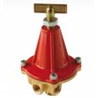
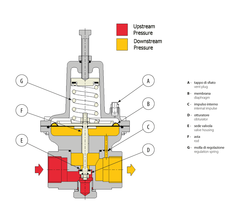
Product information: HPS 100 regulator is direct acting type, controlled by a diaphragm and counter spring. HPS 100 regulator is “top entry” design, which allows an easy maintenance without removing the body from the line.
|
TECHNICAL FEATURES |
|
|
Body size |
1" |
|
Connections |
threaded EN 10226 o NPTF
flanges (on request) PN16-PN40 |
|
Inlet pressure range |
0,5 ÷ 20 bar / 7,5 ÷ 290 psi |
|
Outlet pressure range |
500 ÷ 2800 mbar / 7,25 ÷ 40 psi |
|
Accuracy class AC% |
20 |
|
Closing pressure class SG% |
up to 20 |
|
Design temperature Ts |
-20 ÷ +60 °C |
|
Design pressure |
200 bar / 290 psi |
|
Acceotable gases |
Natural gas, town gas, lpg, nitrogen, air non-corrosive gas |
|
Satefy devices |
Built-in relief valve (optional) |
|
Reference standards-approvals |
En 334 |
|
SAND. MATERIALS |
|
|
Body |
Aluminium "anticordal" |
|
Covers |
Aluminium cast alloys AI Si11 Cu2 (Fe) EN AC 46100 |
|
Diaphragm |
Reinforced rubber 555N - Ag125 AF |
|
Valve seat |
Aluminium UNI EN 573 EN AW 2011 |
|
Shutter |
Brass CuZn39Pb3 EN12164 |
|
Reinforced gasket |
Vulcanized rubber |
|
Balanced diaphragm |
Synthetic rubber with canvas |
|
Seals |
Nitrile rubber O-rings NBR |
|
Springs |
EN 10270 zinc plated carbon steel |
|
DIMENSIONS AND WEIGHTS |
|
|
Flanged
PN16/PN40
ANSI150/ANSI300 |
Threaded
ANSI/ASME B.1.20.1 |
Threaded
EN 10226 |
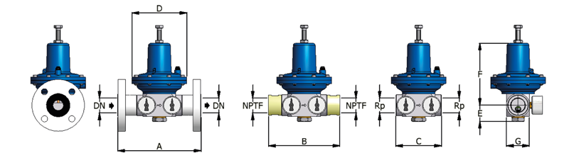 |
CODICE
HPS |
CONNECTIONS |
A
(mm) |
B
(mm) |
C
(mm) |
D
(mm) |
E
(mm) |
F
(mm) |
G
(mm) |
Pesi |
|
100 |
Flanged |
DN25
X
DN25 |
183 |
|
|
120 |
25 |
140 |
50 |
4,5 |
Threaded
ANSI/
ASME B1.20.1 |
NPTF
1"X1" |
|
156 |
|
2 |
Threaded
EN 10226 |
Rp
1"x1" |
|
|
100 |
1,5 |
|
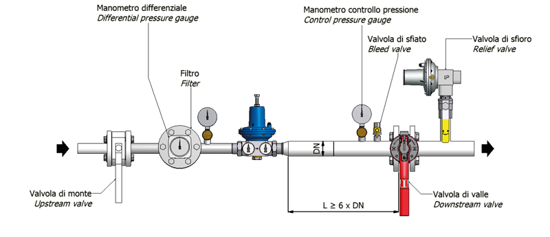
TYPICAL NSTALLATION |
|
 |
|
OPERATION AND COMPONENTS |
|
 |
|
FLOW CAPACITIES |
|
|
HPS 100 - MP : 300-750 MBAR |
|
Intel pressure Pu |
Gas natural portata-capacity Q[stm3/h]
AC = 20% |
LPG/GPL portata - capacity Q [Kg/h]
AC = 20% |
|
1 |
bar |
54 |
65 |
|
1,5 |
bar |
85 |
100 |
|
2 |
bar |
100 |
120 |
|
2,5 |
bar |
115 |
140 |
|
3 |
bar |
130 |
160 |
|
3,5 |
bar |
145 |
175 |
|
4 |
bar |
160 |
195 |
|
5 |
bar |
180 |
215 |
|
HPS 100 - TR : 800-1750 MBAR
|
|
Intel pressure Pu |
Gas natural portata-capacity Q[stm3/h]
AC = 20% |
LPG/GPL portata - capacity Q [Kg/h]
AC = 20% |
|
1 |
bar |
45 |
55 |
|
1,5 |
bar |
75 |
90 |
|
2 |
bar |
100 |
120 |
|
2,5 |
bar |
135 |
160 |
|
3 |
bar |
160 |
195 |
|
3,5 |
bar |
175 |
210 |
|
4 |
bar |
200 |
240 |
|
5 |
bar |
230 |
275 |
HPS 100 - TR : 2000-2500 MBAR |
|
Intel pressure Pu |
Gas natural portata-capacity Q[stm3/h] AC = 20% |
LPG/GPL portata - capacity Q [Kg/h] AC = 20% |
|
2,5 |
bar |
55 |
65 |
|
3 |
bar |
85 |
100 |
|
3,5 |
bar |
135 |
160 |
|
4 |
bar |
160 |
195 |
|
6 |
bar |
230 |
275 |
The above tables give the maximum flow capacity - in m3/h at standard conditions of absolute pressure of 1.013 bar and 15°C temperature.
NOTES:
Capacity Q [m3/h] = referred to Natural Gas at lowest value of setting range
Conversion to: LPG capacity in kg/h= multiply by 1,2
Azote capacity = multiply by 0,789
AC = accuracy class
Regulators must not exceed 20 m/s speed flow on outlet.
|